Adder cmos circuit diagram transistor fa 28t transistors implementation edacafe using transmission gate power fig phdthesis www10 book Edacafe: power, accuracy and noise aspects in cmos mixed-signal Binary adder subtractor bit subtraction addition operation which value either
EDACafe: Power, accuracy and noise aspects in CMOS mixed-signal
Circuit diagram of a one-bit full adder using the proposed technique in Adder bit logisim using circuit cs lab1 cornell labs courses edu build create re ta sub ask Full adder conbinational circuit
4-bit binary adder-subtractor
Adder simplificationAdder mosfet comparative 10t 45nm 14t Block diagram of basic full adder circuitCircuit combinational circuitverse tutorialspoint multiplexers adders.
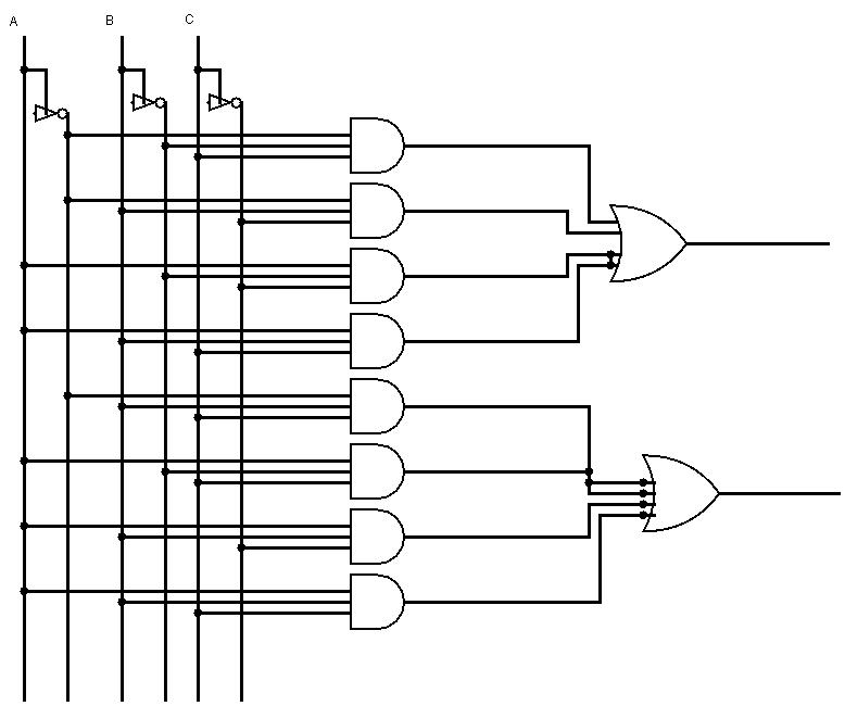
Adder circuit schematic diagramCs 3410 spring 2018 lab 1 Vhdl tutorial – 10: designing half and full-adder circuitsFull-adder circuit, the schematic diagram and how it works – deeptronic.

Adder vhdl circuits truth ckt
Full-adder circuit, the schematic diagram and how it works – deeptronic .
.


Adders | CircuitVerse

Full-Adder Circuit, The Schematic Diagram and How It Works – Deeptronic

CS 3410 Spring 2018 Lab 1

4-bit binary Adder-Subtractor - GeeksforGeeks

Circuit diagram of a one-bit full adder using the proposed technique in

Full Adder Conbinational Circuit | All Computer Topics

Full-Adder Circuit, The Schematic Diagram and How It Works – Deeptronic

VHDL Tutorial – 10: Designing half and full-adder circuits